
products categories
Spectroscopic ellipsometry (SE) is a widely used optical technique for characterizing a broad range of materials, including bulk materials, thin films, coatings, and layers both on the surface and embedded within the material. It provides valuable information about the optical properties of materials by analyzing the change in polarization state of light reflected or transmitted through the sample.
The choice of wavelength range in spectroscopic ellipsometer depends on the specific application and the properties of the materials being studied. The infrared (IR) wavelength range is particularly interesting and relevant because it offers unique insights into material behavior that differ from observations in the ultraviolet (UV) and visible wavelength ranges.
In the IR range, materials exhibit distinct features and behaviors. For example, non-doped semiconductors are often transparent in the IR region, allowing for the analysis of their optical properties with minimal interference from absorption effects. Dielectrics, on the other hand, have characteristic absorption bands in the IR range, which can provide valuable information about their composition and molecular structure. Metals and doped semiconductors exhibit what is known as the Drude absorption tail, which arises from the free electron response in these materials.
InfraRed Spectroscopic Ellipsometer (IRSE) capitalizes on these unique characteristics of materials in the IR range. It enables the comprehensive characterization of various material properties, including structural parameters such as layer thickness, interface properties, surface roughness, and the presence of contaminants. By measuring the change in polarization state of light in the IR range, InfraRed Spectroscopic Ellipsometer, IRSE can extract crucial optical information, such as the refractive index, extinction coefficient, and optical constants of the materials under investigation.
Moreover,InfraRed Spectroscopic Ellipsometer (IRSE) can also provide insights into the electrical properties of materials. By analyzing the ellipsometric data obtained in the IR range, it is possible to extract information about the material's electrical conductivity or resistivity, which can be particularly useful for the study of conductive thin films, doped semiconductors, or metallic layers.
Furthermore, InfraRed Spectroscopic Ellipsometer (IRSE) offers the potential to gather chemical information about the materials being analyzed. By examining the absorption bands in the IR spectrum, it is possible to identify characteristic vibrational modes and chemical bonds present in the sample, aiding in material identification, composition analysis, and chemical characterization.
In summary, InfraRed Spectroscopic Ellipsometer (IRSE) expands the capabilities of spectroscopic ellipsometer to the infrared wavelength range, allowing for a comprehensive characterization of materials. It enables the determination of structural parameters, optical properties, electrical conductivity, and even chemical information. By leveraging the distinct behavior of materials in the IR range, InfraRed Spectroscopic Ellipsometer (IRSE) provides valuable insights for a wide range of applications, including materials science, thin film research, semiconductor development, and chemical analysis.
The measurement principle of an infrared spectroscopic ellipsometer (IRSE) involves directing infrared light onto the sample surface at various angles of incidence and analyzing the reflected light. The ellipsometric parameters, such as the amplitude ratio (Ψ) and phase difference (Δ) between the p-polarized and s-polarized components of the reflected light, are measured.
The acquired data with InfraRed Spectroscopic Ellipsometer (IRSE) is then compared to a model that incorporates the optical properties and layer thicknesses of the sample. Through a fitting procedure, the model parameters are adjusted until the calculated ellipsometric parameters match the experimental values. This allows the determination of the sample's optical constants and layer properties.
- Horizontal sample placement
- Affordable, Low Cost
- Compact design
- Easy to use with Window based software; scientific mode for advanced users and operator mode for routine/daily operations
- Variable Incident angles (VASE, variable incident angle spectroscopic ellipsometer))
- User definable resolution
- Fast measurement based on FTIR technique
- Comprehensive optical constants database and model recipes
- Advanced TFProbe Software allows user to define layers with NK table, dispersion or EMA mixture/composites with index grading, and surface/interface roughness...
- Upgradable and reconfigurable with Various options and accessories
- Michelson interferometer with continuous dynamic alignment for long-term stability
- Long Lifetime Infrared Source
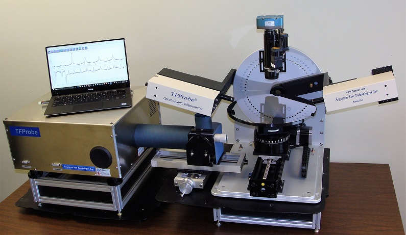
- Model: TFProbe IRSE
- Light Source: Long Lifetime Polaris™ Infrared Source
- Spectrometer:
- Michelson interferometer Dual ports output
- Ge on KBr beamsplitter
- High-precision HeNe reference laser
- Continuously variable iris aperture
- BaF2 coated KBr windows
- Variable Incident angle: 20 – 90 degree at 5-degree interval
- Angle Change Mode: Manual with preset slots
- Polarizing Optics: Motorized Grid IR Polarizers
- Detector: TE-cooled DLaTGS detector with KBr window
- Stage: High Precision Z stage with tilting adjustment
- Sample Plate: 200mm diameter, Horizontal placement
- Communication: USB 2.0
- Computer: Intel i5 processor, 8GB ram and 500GB Hard Drive with Keyboard and Mouse
- Monitor: 22” LCD Monitor
- Software: TFProbe 3.3 for InfraRed Spectroscopic Ellipsometer (IRSE)
- Spectral range: 350 - 7400 cm-1
- Spectral Resolution: 0.5 - 32 cm-1
- Wavelength Precision: Better than 0.01 cm-1
- Scanning Velocity: 0.158 – 6.28 cm/sec
- Spot size: 1 - 5 mm
- Angle of incidence: 20° to 90°, 5o interval
- Measurement time: 5 sec/site to several min, user definable
- Measurement precision: better than 1Å for Thermal SiO2/Si
- Detector: MCT-A (400 – 11700cm-1); MCT-B (600 – 11700cm-1); MCT-C (800 – 12500cm-1)
- Incident Angle: Motorized Goniometer for changing incident angle automatically at 0.01 degree
- Sample Holder: up to 450mm size
- Motorized mapping stage at X-Y or Rho-Theta to cover up to 450mm wafer size
- Reflection and/or transmission measurement
- Heating and Cooling Stage
- Digital Vision with imaging functions
- Focused beam set up for small area measurement
- Work with Window based operating systems
- User friendly and easy to use interface
- Integrated all-in-one functions for Simulation, Hardware Configuration and Calibration, Data Acquisition, Regression and Graphics Presentation
- Simulation on photometry and ellipsometry on spectroscopic, Variable Angle or combined parameters
- Comprehensive Optical Constants database, over 300 sets of optical constants for various materials included
- Unlimited layers in layer stack can be set up
- Each Layer or film can be defined from NK table (Library database), dispersion, interface, surface roughness or composite mixture model (EMA, effective media approximation)
- Capable to define inhomogeneous layer with linear, exponential, Gaussian etc profile
- Various dispersion model available such as Cauchy, Sellmeier, Gaussian, Tauc-Lorentz, Drude IR, Exponential, model dielectric functions etc, plus user can add unlimited absorption bands into dispersion
- Support Anisotropic layers with dispersion definition
- EMA Model can be defined with 2 or 3 materials mixture with Bruggeman or Maxwell-Garnett, both component’s volume fraction and depolarization factors can be set as variable
- Advanced regression control on single set or multiple sets data, incident angle, angle deviation, fitting range modification, backside reflection factors, weighted consideration on either ellipsometry parameters with Marquardt-Levenberg or Simplex algorithms
- 2D and 3D graphic presentation
- User level control with password protected levels
- Support both CCD-based array or Scanning monochromator detecting system
- Flexible recipe setup interface from simple measurement to one-click to results full recipe
- Support and communicate with various type of CCD based array detector systems
- Allow to acquire ellipsometry, reflection and transmission data if licensed
- Allow for time series with fixed time step or continuous measurement which is suitable for real time monitoring and inline metrology applications
- Advanced optical constants editor and mapping profile setup
- Operating systems: Win XP, Win Vista or Win 7(32Bit), Win 8(64bit), Win 10(64bit)
- Functions: Simulation, Hardware Configuration and Calibration, Data Acquisition, and Regression
- Application: Photometry and Ellipsometry
Overall, infrared spectroscopic ellipsometer (IRSE) is a valuable tool for characterizing the optical properties and composition of materials, offering insights into their structure, functionality, and performance. Some of the key applications of infrared spectroscopic ellipsometer include:
- Thin film characterization: It can determine the thickness, refractive index, and composition of thin films in various fields such as semiconductor industry, optics, and surface coatings.
- Chemical analysis: It provides information about the molecular structure and composition of organic materials, polymers, and biomolecules.
- Surface and interface studies: It helps in understanding the properties of surfaces and interfaces, including their roughness, adsorption, and thickness.
- Material research and development: It aids in the investigation of new materials and their optical properties, enabling the optimization of material synthesis and processing methods.
- Bulk materials: Glasses, PET, Doped silicon
- Silicon epitaxial layers:
- doping profile
- thin epilayers (< 1 um)
- low contrast N-/N epilayers
- Semiconductor epilayers (GaAs, Insb, SiC, SiGe, CdHgTe, …)
- Dielectric films characterization
- Silicon layers for FPD applications
- Monitoring of a-Si:H process quality (CVD, ELA process)
- Si-H and N:H relative content in SiN layers
- ITO films: optical and electrical characterization
- BPSG, PSG: boron and phosphorus concentration
- Low-k materials:
- Organic low-k material.
- Determine the thickness and optical constants
- Calculate the carbon content (% C).
- Determine the water content before and after annealing
- SiOC:H: carbon content and porosity.
- Porous SiO2: thickness, porosity, water content.
- Organic low-k material.
- Trench, Vias, Recess and shallow trench isolations (STI)
- SOI Optical Waveguides: thickness measurements.
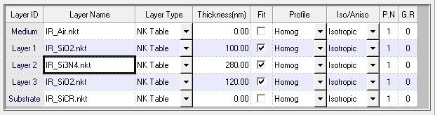
Layer Stack Setup Interface:
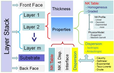
Optical Model Tree:
Note:
1. System configuration and Specifications subject to change without notice.
2. * Film property, surface quality and layer stack dependent
3. Customized system available for special applications
4. TFProbe is registered trademark of Angstrom Sun Technologies Inc.
5. MCT: HgCdTe, Mercury Cadmium Telluride
6. DTGS: Deuterated Triglycine Sulfate
7. DLaTGS: Deuterated Lanthanum α Alanine doped TriGlycine Sulphate